sales@hasco-inc.com
 888-498-3242


23 dBi Standard-Gain Horn Antennas | 18–110 GHz
23 dBi Standard-Gain Horn Antennas from 18 to 110 GHz
Use a stable, band-matched rectangular horn for antenna-range calibration, gain comparison, radiation-pattern measurements and waveguide system development.
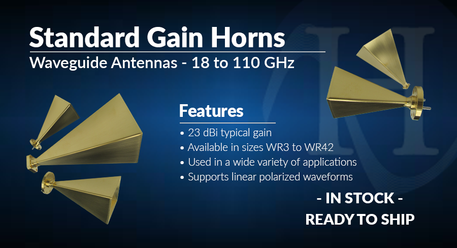
Establish a known reference for gain and pattern measurements.
Standard-gain horns provide a practical reference antenna with predictable directional behavior. Select the horn around the exact test band, mating waveguide and flange—not just the nominal band name.
Frequency coverage
Choose the model whose published range fully covers the measurement band.
Waveguide and flange
Verify WR size, flange designation, alignment and mating hardware before ordering.
Polarization
Orient the rectangular aperture consistently with the required linear polarization.
Test geometry
Plan separation distance, alignment, mounting and reflections around the measurement setup.
Seven standard models cover K through W band.
All models below provide 23 dBi typical gain, 1.10:1 maximum VSWR, vertical linear polarization and a published temperature range of -55°C to +85°C.
HWSGH42-23-ES
WR-42 input · UG-599/U flange
HWSGH28-23-ES
WR-28 input · UG-599/U flange
HWSGH22-23-ER
WR-22 input · UG-383/U MOD flange
HWSGH19-23-ER
WR-19 input · UG-383/U MOD flange
HWSGH15-23-ER
WR-15 input · UG-385/U flange
HWSGH12-23-ER
WR-12 input · UG-387/U flange
HWSGH10-23-ER
WR-10 input · UG-387/U MOD flange
Overlapping bands: adjacent horns overlap in frequency, but their WR inputs and flanges differ. Select the horn that matches the system waveguide and the measurement band.
Match frequency range, input and flange.
| Model | Band | Frequency | Input | Flange | Gain / VSWR |
|---|---|---|---|---|---|
| HWSGH42-23-ES | K | 18-26.5 GHz | WR-42 | UG-599/U | 23 dBi / 1.10:1 max |
| HWSGH28-23-ES | Ka | 26.5-40 GHz | WR-28 | UG-599/U | 23 dBi / 1.10:1 max |
| HWSGH22-23-ER | Q | 33-50 GHz | WR-22 | UG-383/U MOD | 23 dBi / 1.10:1 max |
| HWSGH19-23-ER | U | 40-60 GHz | WR-19 | UG-383/U MOD | 23 dBi / 1.10:1 max |
| HWSGH15-23-ER | V | 50-75 GHz | WR-15 | UG-385/U | 23 dBi / 1.10:1 max |
| HWSGH12-23-ER | E | 60-90 GHz | WR-12 | UG-387/U | 23 dBi / 1.10:1 max |
| HWSGH10-23-ER | W | 75-110 GHz | WR-10 | UG-387/U MOD | 23 dBi / 1.10:1 max |
Reference antennas for calibration, measurement and system integration.
Antenna ranges
Reference gain and calibration work across microwave and mmWave bands.
Pattern measurement
Transmit or receive reference for radiation-pattern testing.
Lens and reflector feeds
Directional feed horns for lens, reflector and offset-feed systems.
Radar and communications
Stand-alone antennas and subsystem development hardware.
Select the horn around the complete measurement setup.
Match frequency to the correct WR input.
Confirm flange, mounting and available clearance.
HASCO is AS9120:B and ISO 9001:2015 certified.
Ask about special-order horns with other gain values.
Request a Standard-Gain Horn Antenna Quote
Include the operating range, WR size, flange, required gain, polarization, quantity, application and requested delivery date.
Start Your Quote RequestCall 888.498.3242 or email sales@hasco-inc.com