sales@hasco-inc.com
 888-498-3242


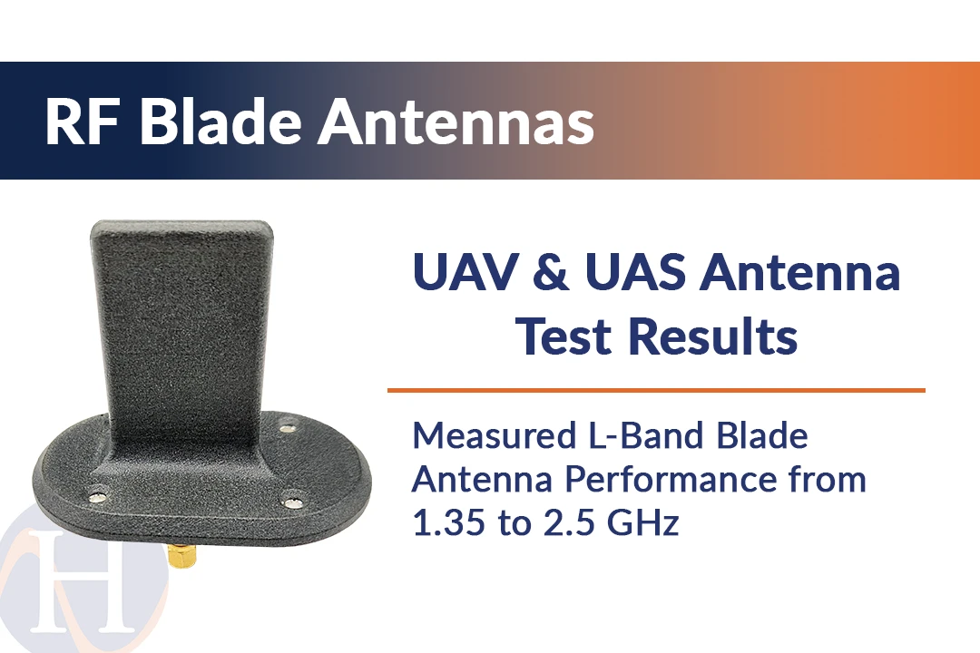
Measured L-Band Blade Antenna Performance from 1.35 to 2.5 GHz
Posted by HASCO RF on 2nd Nov 2026
UAV & UAS ANTENNA TEST RESULTS
Measured L-Band Blade Antenna Performance from 1.35 to 2.5 GHz
Direct far-field testing provides a detailed view of peak gain and radiation-pattern behavior across the operating range of a compact blade antenna developed for unmanned-aircraft applications.

Blade antennas offer UAV and UAS platforms a low-profile option for external RF links. Selection requires more than matching frequency range: radiation-pattern shape, gain across the band and installation sensitivity all affect the link available during flight in service.
Test Scope and Measurement Method
An L-band blade antenna was evaluated at 1.35, 1.60, 1.85, 2.20, 2.30, 2.40 and 2.50 GHz. Testing used a direct far-field method in an antenna chamber. Results included calibrated gain, two-dimensional cuts in the three principal planes, three-dimensional pattern data and tabulated measurement files.
Three controlled installation configurations were measured as repeatable test conditions. Together, they show the antenna’s basic radiation behavior and the performance range observed as its immediate RF environment changed.
Measured Peak Gain Across the Band
The table below summarizes measured peak gain. Configuration A produced the highest result at most test points, ranging from 2.3 to 4.5 dB. Configurations B and C ranged from 0.5 to 3.7 dB and 0.8 to 4.1 dB, respectively.
| Frequency | Configuration A | Configuration B | Configuration C |
|---|---|---|---|
| 1.35 GHz | 2.9 dB | 0.5 dB | 1.4 dB |
| 1.60 GHz | 4.5 dB | 2.5 dB | 3.1 dB |
| 1.85 GHz | 3.4 dB | 1.8 dB | 2.2 dB |
| 2.20 GHz | 2.3 dB | 0.9 dB | 0.8 dB |
| 2.30 GHz | 3.6 dB | 1.9 dB | 2.2 dB |
| 2.40 GHz | 3.8 dB | 3.7 dB | 4.1 dB |
| 2.50 GHz | 3.8 dB | 2.1 dB | 2.3 dB |
The values are measured peak gain for the evaluated test configurations and should not be interpreted
as guaranteed installed-aircraft performance.
The data shows useful gain throughout the measured range, with the strongest result of 4.5 dB occurring at 1.60 GHz in Configuration A. At 2.40 GHz, all three configurations converged within 0.4 dB, producing 3.7 to 4.1 dB. Greater separation appeared at several lower-frequency points, demonstrating that the surrounding installation can affect realized performance differently across the band.
Radiation-Pattern Characteristics
Pattern measurements were collected in the XY, YZ and XZ planes at every test frequency. The azimuth-plane results were generally omnidirectional, a desirable characteristic for many telemetry, command-and-control and compatible communication links where the aircraft heading changes relative to the ground station.
The vertical-plane cuts displayed the expected directional lobes and null regions. Their shape varied with frequency and test configuration, particularly in the lower portion of the band. Three-dimensional results provided additional visibility into coverage above, below and around the mounting plane. For UAV designers, these elevation characteristics can be as important as azimuth coverage because pitch, bank angle and antenna placement influence the orientation of the link during flight.
Applying the Results to UAV and UAS Platforms
The chamber results provide a strong engineering baseline, but they do not replace installed-platform analysis. Ground-plane dimensions, airframe materials, nearby payloads and final antenna location can reshape the pattern or create shadowed directions. Integration reviews should therefore address:
- Required operating frequencies, bandwidth, RF power and link margin.
- Antenna location relative to conductive structures and onboard payloads.
- Azimuth and elevation coverage throughout expected aircraft attitudes.
- Mounting footprint, ground plane, environmental exposure and weight limits.
- Final return-loss, pattern and link testing appropriate to program risk.
HASCO offers L-band blade antenna models covering 1.35 to 2.5 GHz with two-hole and four-hole mounting arrangements. Additional S-band and dual S/C-band models allow engineers to compare options across multiple UAV communication architectures. The best selection begins with the required band and continues through installation-level validation.
Discuss your UAV/UAS Antenna Requirements
Provide the operating band, power, mounting area, airframe details, required coverage and program environment. HASCO can help identify a suitable blade antenna model and the technical information needed for evaluation.
Request Application Assistance