sales@hasco-inc.com
 888-498-3242


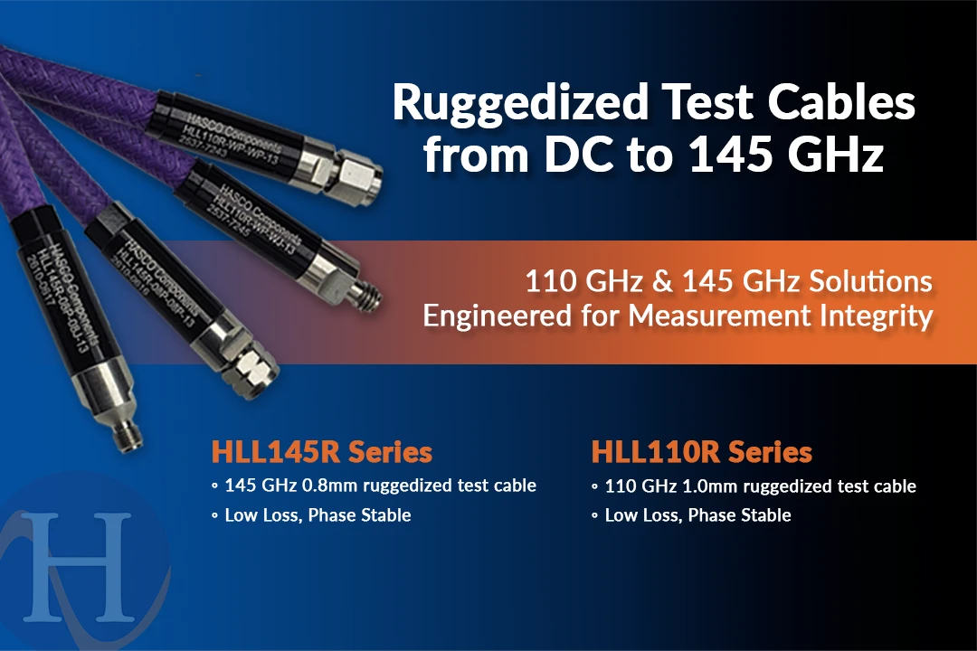
The Cable Is Part of the Measurement: Choosing Between 110 GHz and 145 GHz HLL Test Cables
Posted by HASCO RF on 17th Nov 2026
Ask an RF engineer what limits a millimeter-wave measurement and you will hear about calibration, instruments and device fixtures. The cable tends to come up last, even though it sits in every test path. At 110 GHz and beyond, that is a habit worth breaking. This article looks at two ruggedized options from HASCO, the HLL110R and HLL145R, and how to decide which one belongs in your setup.
Why mmWave cables ask more of you
Loss rises with both frequency and length, so every extra inch of cable costs more at 140 GHz than it does at 40. Connector interfaces shrink as frequency climbs, which makes them less forgiving of rough handling. And because test cables get flexed, routed and reconnected all day, the cable has to stay stable while it moves.
That combination is what HASCO's HLL family targets: low loss, mechanical protection and stable performance in demanding mmWave setups. Both versions are 50 Ω assemblies with ruggedized construction, so the cable body takes the wear instead of your measurement.
Two cables, two jobs
The HLL110R uses 1.0mm connectors and covers DC to 110 GHz. It pairs a multi-layer copper spiral with braided armor, and HASCO publishes a VSWR of 1.35:1 at 110 GHz, amplitude stability within ±0.2 dB and phase stability within ±8° versus flexure. That last figure matters in daily use: a cable that shifts phase every time it moves forces you to recalibrate or accept the error. Representative lengths run from 6 to 48 inches, plus 1m, with a 30mm minimum bend radius.
The HLL145R moves to 0.8mm interfaces and extends coaxial measurements through 145 GHz. It is a low-loss, phase-stable, ruggedized cable with a published maximum VSWR of 1.50:1, a 50mm repeated bend radius and 1,000-cycle connector durability. Representative lengths run from 4 to 24 inches. Both families are rated for -55°C to +85°C.
Which one do you actually need?
Start with the highest frequency you will measure, and use the lowest-frequency interface that fully covers the test. If you stop at 110 GHz, the HLL110R is the practical choice. If the setup extends past 110 GHz toward 145 GHz, you need the 0.8mm interface and the HLL145R.
Then look at the rest of the path. Match connector type and gender to your instrument and device ports so you are not stacking adapters; male-to-male, male-to-female and female-to-female configurations are all options. Pick the shortest length that allows safe routing, because insertion loss grows with length. Finally, check your real routed path against the bend radius, 30 mm for the HLL110R and 50 mm for the HLL145R. Frequency alone should not make the decision.
Treat the connectors like part of the instrument
A precision cable only performs if its connectors are in good shape. Inspect and clean them before mating, align them carefully, torque them properly, and never use the cable body to rotate a precision connector. Those habits protect the connector durability HASCO publishes and keep results repeatable from one session to the next.
Typical uses include VNA measurements through 110 or 145 GHz, characterizing amplifiers, mixers, multipliers and interconnects, production test where cables are reconnected and rerouted constantly, and mmWave development for radar, communications, imaging and research systems. HASCO is AS9120:B and ISO 9001:2015 certified.
Get your quote
To get a quote, send HASCO your maximum test frequency, the connector interface and gender at each end, required length, minimum routing radius, quantity and delivery date through the quote request form, or call 888-498-3242 or email sales@hasco-inc.com. Full details are on the HLL110R and HLL145R product page.