sales@hasco-inc.com
 888-498-3242


Southwest Microwave end and vertical-launch connectors

High-Frequency End- & Vertical-Launch Connectors
Create a controlled transition from the PCB to precision coax for designs through 40, 67 and 110 GHz, with selected configurations supported by test data through 145 GHz.
Board-edge access or a transition through the board surface?
Both families transition planar circuitry to coax. Select the geometry around board access, available footprint, mechanical loading and the intended transmission-line structure.
End-launch connectors
Mount at the board edge. Multiple block widths, profiles, transition sizes and thread-in configurations support evaluation boards, modules and reusable test hardware.
Browse end-launch connectors →Vertical-launch connectors
Mount through the board surface where edge access is unavailable or the launch must be positioned within the PCB area. Compression-mount designs are removable and reusable.
Browse vertical-launch connectors →Select the connector family around the operating band.
The representative vertical-launch models below provide a starting point. Confirm exact frequency limits, drawing revision, board compatibility and current availability before release.
| Model | Interface / geometry | Published coverage | Typical starting point | Action |
|---|---|---|---|---|
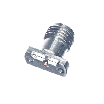
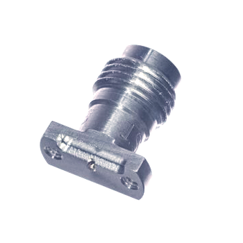
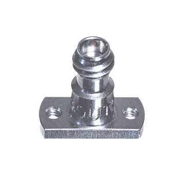
| 10359-002J | 2.92mm / vertical | DC-40 GHz | Ka-band boards and fixtures | Get quote → |
| 18359-001J | 1.85mm / vertical | DC-67 GHz | V-band and broadband characterization | Get quote → |
| 24359-001J | 1.0mm / vertical | DC-110 GHz | W-band component evaluation | Get quote → |
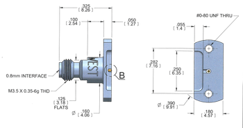
| 26359-001J | 0.8mm / vertical | Test data through 145 GHz | Designs extending beyond 1.0mm coverage | Get quote → |
Model-specific limits: “40-145 GHz” describes the campaign range, not a universal rating. The 145 GHz test data applies to the featured 0.8 mm vertical launch. Individual end- and vertical-launch products have their own published limits.
Keep the launch from becoming the weak point.
Match interface to frequency
Choose 2.92, 1.85, 1.0 or 0.8mm around the operating band and applicable model data.
Control PCB geometry
Substrate, stackup, trace width, copper geometry, vias and ground continuity influence performance.
Review before fabrication
Use the applicable drawing, recommended footprint, simulations and test data before board release.
Plan the coax connection around the hardware.
Evaluation boards
Reusable launches for device and MMIC evaluation.
RF and mmWave modules
Board-edge or surface access matched to the enclosure.
Broadband testing
Transitions for fixtures and characterization hardware.
Prototype revisions
Removable connectors that support iterative development.
Support from connector selection through procurement.
Match interface, frequency and launch geometry.
Review stackup, trace geometry and board thickness.
HASCO is AS9120:B and ISO 9001:2015 certified.
Confirm availability, quantity and required delivery.
Request a PCB Launch Connector Quote
Include the interface, operating band, PCB material and stackup, trace geometry, board thickness, launch orientation, quantity and required schedule.
Start Your Quote RequestCall 888.498.3242 or email sales@hasco-inc.com